
Last time we recorded the video output of the C64 using a digital storage oscilloscope and the LM1881 sync stripper. Here we’ll take a closer look at the luma signal and turn it into a black-and-white image of the screen.
A PAL video stream can be thought of as a sequence of images (frames) that are transmitted line by line. Each horizontal line is transmitted left to right, and the lines of a frame are transmitted from top to bottom. Or, sort of… PAL uses what is called interlaced scan: Two consecutive fields are transmitted instead of a frame. The first field contains the odd numbered lines, the second field the even numbered lines. Each field covers the entire display; persistence of vision takes care of filling in the gaps.
Interlaced scanning is used to double the perceived frame rate while using the same bandwidth as non-interlaced (or progressive) scanning. The frame rate of a PAL video stream is 25 frames/s, but this is perceived as 50 frames/s.
The C64 and other home computers of the same era, however, output a kind of progressive scan PAL video stream. A standard PAL video frame contains 625 lines, and so each field contains 312.5 lines. By using a modified vertical synchronization signal, the C64 outputs odd fields only. Even fields are replaced by odd fields, and the fields themselves are truncated to 312 lines. The result is a non-standard PAL video stream with 312 lines per “frame” (odd field), at 50 frames/s, or half the vertical resolution at double the frame rate compared to a standard PAL video stream.
We will use the term frame instead of odd field, since in the case of the C64 the concept of a field is an implementation detail. The C64 effectively hijacks the PAL video standard to output frames of 312 lines at 50 frames per second. For the same reason, we will use consecutive line numbers starting from 1, instead of using odd line numbers.
To display the a PAL video stream, we need to split the video signal into frames somehow, and split each frame into lines. Luckily for us, the video signal contains synchronization signals also known as sync pulses, to indicate the start of each frame as well as the start of each line. These sync pulses are embedded into the luma signal. The structure of the horizontal sync pulse is simpler than that of the vertical sync pulse, so let’s start there.
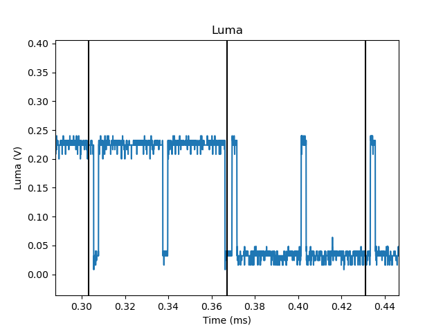
The figure below shows a line of active video including the sync pulse. The sync pulse of the next line, as well as a small part of the next line itself, is also visible. The squibbles in the center are pixels of on screen text.
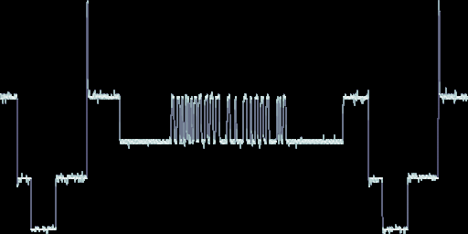
A horizontal scan line.
The start of the horizontal sync pulse is the falling edge towards the sync level, which is the lowest voltage level in the video signal. This is approximately 0V in case of the C64; standard PAL video uses -0.3V.
By detecting these horizontal sync pulses, we should be able to turn the luma signal we recorded earlier into a two-dimensional image. The value of each luma sample determines the brightness of the corresponding pixel. The horizontal sync pulses will be used to determine when to start a new line in the image.
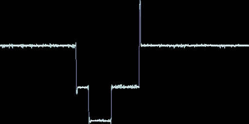
Horizontal sync pulse.
The Python script shown below performs this conversion. It starts by reading the
entire recording into memory. Then it loops over all luma samples in the
recording. Each sample is appended to the line array, which contains
samples that belong to the same line. If a falling edge towards the sync level
is detected, a new line is started and appended to the image. To detect falling
edges, each sample is compared against a threshold. If the sample value is
smaller than the threshold, the sample is considered to be part of a sync
pulse. If the current sample value is smaller than the threshold, but the
previous sample value was larger, then a falling edge has been detected.
Because of rounding, and because vertical sync pulses are not being handled
properly, the number of samples in a line may vary. To display the image using
matplotlib, we need to convert it to a simple rectangular array of
pixels. To this end, a new image is created of which the width is equal to
number of samples in the longest line. This image is initialized to black, and
then each line is copied into it.
#!/usr/bin/env python3

import h5py
import matplotlib.pyplot as plt
import numpy as np
import sys

SYNC_THRESHOLD = 0.1

def main(filename="capture.h5"):

    with h5py.File(filename, "r") as hdf5_file:

        sample_rate = hdf5_file.attrs["sample_rate"]
        luma = hdf5_file["luma"][:]
        chroma = hdf5_file["chroma"][:]

    prev_sync = False

    image, line = [], []
    image.append(line)

    for sample in luma:

        sync = sample < SYNC_THRESHOLD
        new_line = sync and not prev_sync
        prev_sync = sync

        if new_line:
            line = []
            image.append(line)

        line.append(sample)

    num_y = len(image)
    num_x = max((len(line) for line in image), default=0)
    np_image = np.zeros((num_y, num_x))
    for y, line in enumerate(image):
        np_image[y,:len(line)] = line

    plt.figure()
    plt.imshow(np_image, cmap="gray", vmin=0.0, vmax=1.0)
    plt.show()

if __name__ == "__main__":

    main(*sys.argv[1:])
The result is an image that shows one complete frame, followed by a partial frame. The short lines in between both frames are caused by trying to interpret the vertical sync pulse as lines of video. Still, the C64 basic screen is clearly recognizable in the image. It is stretched horizontally because the video signal in this recording was sampled at 20 MHz, while the C64 pixel clock is about 7 MHz.
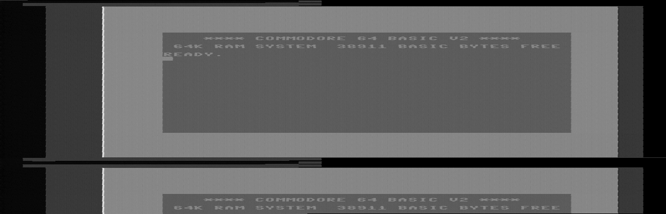
Image created from the recorded luma signal using horizontal sync pulses.
We’ll come back to the difference in sample rate later. First, let’s examine the vertical synch pulse. The vertical sync “pulse” is actually a sequence of different sync pulses: 6 short sync pulses, followed by 6 long sync pulses, and then again 6 short sync pulses (see the image below).
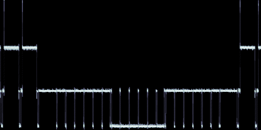
Vertical sync pulse sequence.
The short sync pulses are half the duration of a normal (horizontal) sync pulse, whereas the long sync pulses are half the duration of a horizontal line, minus a short sync pulse duration. The entire vertical sync pulse sequence takes exactly 9 horizontal lines.
The short sync pulses are called equalization pulses. The positive going short pulses that occur in the section of vertical sync pulse sequence that contains long sync pulses are called serrations or serration pulses. Without these serrations we would be left with a single long sync pulse that lasts for 3 horizontal lines. Presumably, a lack of horizontal sync lasting several lines could confuse receivers.
The 6-6-6 vertical sync pulse sequence is unexpected. The PAL standard uses 5-5-5 for the odd field and 5-5-4 for the even field. Only the NTSC standard uses a 6-6-6 vertical sync sequence, for the odd field. Maybe TVs were not too picky? Reusing the NTSC vertical pulse sequence for PAL machines may have saved some additional circuitry.
There seems to be some more reuse going on… The figure below shows a detail of the vertical sync sequence where it changes from short sync pulses to long sync pulses. The black vertical lines show the start of hortizontal lines for reference. Notice that the long pulse sequence is just a negated (flipped) version of the short pulse sequence.
Vertical sync pulse.
Below is another view of roughly the same region with the standard PAL vertical sync sequence overplotted in red. Compared to the standard sequence, the C64 outputs an additional serration at the start of the first long sync pulse. Also, the short pulses are late by one short sync pulse duration, and the serrations are both late and too short. None of this seems to be very critical. For example, the Atari 180XE replaces the whole vertical sync pulse sequence with just three long pulses!
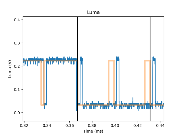
Vertical sync pulse.
To robustly detect vertical sync, I decided not to make too many assumptions about the structure of the pulse sequence. The code shown below assumes that there will be at least one long pulse (> 10 us), followed by at least one short pulse (< 3 us). The only tuning parameter is the sync threshold.
class SyncDetector:

    def __init__(self, sample_rate, threshold):

        self._sample_rate      = sample_rate
        self._threshold        = threshold
        self._sync_count       = 0
        self._short_sync_count = 0
        self._long_sync        = False
        self._short_sync       = False
        self._normal_sync      = False
        self._vertical_sync    = False

    def input(self, luma):

        sync = (luma <= self._threshold)

        if sync and self._normal_sync and self._vertical_sync:
            self._vertical_sync = False

        if sync:
            self._sync_count += 1
        else:
            if self._sync_count > 0:
                sync_duration_us = self._sync_count * 1e6 / self._sample_rate

                if sync_duration_us > 10.0:
                    # Long sync pulse.
                    self._long_sync = True
                    self._normal_sync = False
                    self._short_sync = False
                    self._vertical_sync = True

                elif self._long_sync:
                    self._long_sync = False
                    self._short_sync = True
                    self._short_sync_count = self._sync_count

                elif self._short_sync:
                    if self._sync_count > 1.5 * self._short_sync_count:
                        self._short_sync = False
                        self._normal_sync = True

                elif not self._vertical_sync:
                    if self._sync_count < 1.5 * self._short_sync_count:
                        self._normal_sync = False
                        self._vertical_sync = True

            self._sync_count = 0

        return sync, self._vertical_sync
Each luma sample is passed through the sync detector; for each sample, the detector returns two boolean values: The first value indicates whether the sample belongs to any sync pulse (horizontal or vertical), the second whether it belongs to a vertical sync pulse.
The sync detector counts the number of samples in each sync pulse. If this number corresponds to a pulse duration longer than 10 us, we’ve detected a long sync pulse, and so we know we are within a vertical sync pulse sequence. If the sync pulse is shorter than 10 us, but the previous pulse was a long pulse, we have found the start of the second sequence of short sync pulses that are part of the vertical pulse sequence. We record the duration of the short sync pulse for later reference. As soon as we detect a sync pulse shorter than 10 us, but significantly longer than a short sync pulse, we know we’ve detected the start of the first line of video after the vertical sync pulse.
If we are not inside a vertical pulse sequence and we detect a sync pulse significantly shorter than the normal sync duration, we have found the start of the first sequence of short sync pulses that are part of the vertical sync pulse sequence.
Using the sync detector, we can now split the recorded samples into separate frames. If the previous sample was part of a vertical sync pulse, and the current sample is not, we have found the start of a new frame.
#!/usr/bin/env python

import math
import numpy as np
import h5py
import sys

from matplotlib import pyplot as plt

F_COLOR_SUB_CARIER = 4.43361875e6
F_MASTER_CLK = F_COLOR_SUB_CARIER * 4.0
F_CPU = F_MASTER_CLK / 18.0
F_VIC_II = F_CPU * 8.0
T_HLINE_US = 1e6 / F_VIC_II * 63 * 8

SYNC_THRESHOLD = 0.1

class LumaDecoder:

    def __init__(self, sample_rate, threshold):

        self._sync_detector = SyncDetector(sample_rate, threshold)
        self._sync = False
        self._vertical_sync = False

        self._num_x = math.ceil(63 * 8 * sample_rate / F_VIC_II)
        self._num_y = 312 - 9 - 1 - 1
        self._frame = None
        self._x = 0
        self._y = 0

    def input(self, luma):

        frame = None

        sync, vertical_sync = self._sync_detector.input(luma)

        new_frame = not vertical_sync and self._vertical_sync
        self._vertical_sync = vertical_sync

        new_h_line = sync and not self._sync
        self._sync = sync

        if vertical_sync:
            return None

        if new_frame:
            frame = self._frame
            self._frame = np.zeros((self._num_y, self._num_x))
            self._y = 0

        if self._frame is None:
            return None

        if new_h_line:
            self._x = 0

        if new_h_line and not new_frame:
            self._y += 1

        if self._x < self._num_x and self._y < self._num_y:
            self._frame[self._y, self._x] = luma
            self._x += 1

        return frame

def main(filename):

    with h5py.File(filename, "r") as hdf5_file:

        sample_rate = hdf5_file.attrs["sample_rate"]
        luma = hdf5_file["luma"][:]

    decoder = LumaDecoder(sample_rate, SYNC_THRESHOLD)

    for sample in luma:
        frame = decoder.input(sample)
        if frame is None:
            continue
        plt.figure()
        plt.imshow(frame, cmap="gray", vmin=0.0, vmax=1.0, aspect=(sample_rate / F_VIC_II))

    plt.show()

if __name__ == "__main__":

    main(*sys.argv[1:])
The result is a more faithful reconstruction of the C64 basic screen than the
previous attempt. The horizontal stretch was compensated by setting the aspect
ratio in the call to imshow. The luma signal was sampled at 20 MHz, while the
VIC-II pixel clock is 7.882 MHz (approximately). This stretches the horizontal
axis by a factor of 20 / 7.882 = 2.537. Setting this as the aspect ratio
stretches the vertical axis by the same amount.
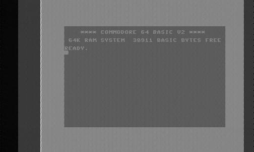
Image created from the recorded luma signal using both horizontal and vertical sync pulses.
The decoded frame contains 301 lines. A frame including the vertical sync pulse sequence consists of 312 lines. So what gives? The decoder discards the vertical sync pulse sequence, which covers 9 lines. The sync decoder then drops the first line of active video, because it does not start a frame until it observed a regular horizontal sync pulse. We also drop the last line of active video because it has an uncommon length. The line is longer than a regular line because the succeeding short sync pulse is late.
The white vertical line at the start of the C64 border is a real feature generated by the VIC-II. Most monitors will not show it unless the picture is panned hard to the right.
The jagged edges seen along vertical lines are probably sampling artifacts. My guess is that these are sub-pixel shifts caused by the sampling frequency not being synchronized to the VIC-II pixel clock in any way. See for example the right edge of the left border.
Next up, we will turn our attention to the chroma signal to recover some nice C64 blues.
Related links:
- A description of PAL (and NTSC) video timing.
- A complete reference to the specified and unspecified properties of the VIC-II.
- A detailed description of the VIC-II pixel aspect ratio.
- A recording of the C64 BASIC screen.
- A Python script to decode captured luma signals stored in HDF5 format.